

Upgrading Traction Drive Controller
- Project Overview
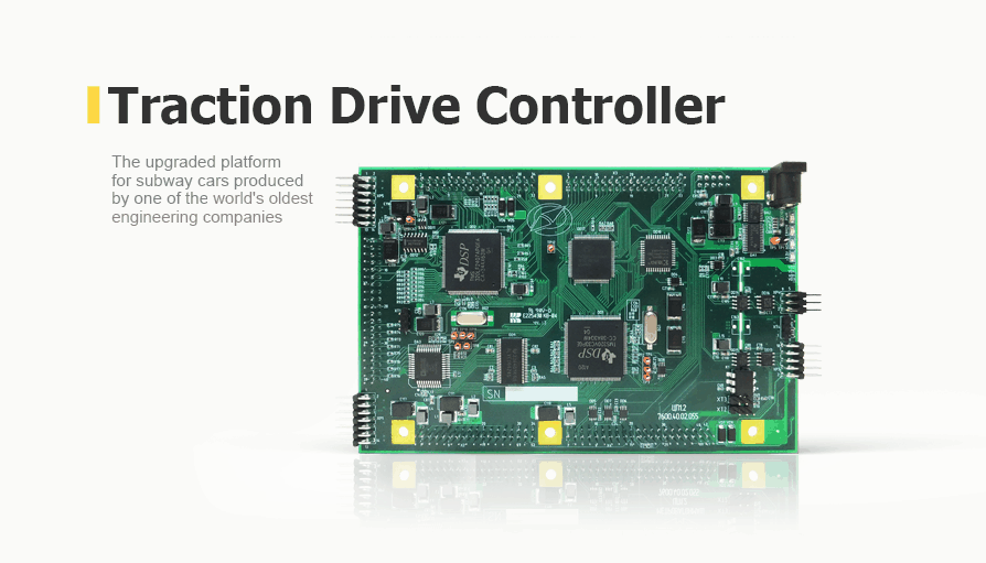
Commissioned by a large public transportation company, we upgraded the controller of an electric traction device that was developed for subway carriages made more than 10 years ago.
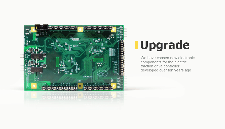
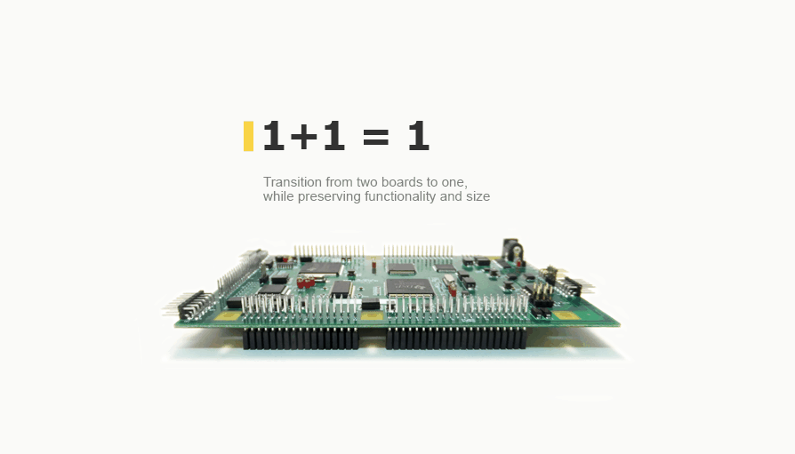
Promwad engineers selected a new component base for the outdated platform and involved only one PCB instead of two, at the same time necessary functions and size remained. Software adjustments were minimal.
As a result of the project the customer was able to reduce costs for mass production, and could use modern electronic components.
Results of the project During the project the experts from Promwad completed the following tasks:
— Hardware platform and software development
— Software and hardware platform upgrade
— Selection of electronic components and BOM optimization
— Development of design documentation for serial production- How It's Made
Objective
Upgrading the current hardware platform of the electric traction drive controller developed over ten years ago with new electronic components. All the functionality of the updated platform should be implemented on a single printed circuit board (PCB) with minimal software adjustments.
Solution
1. Circuit design
The objective of the project is to upgrade the existing hardware platform of the controller while preserving the original functionality in accordance with the customer’s requirements and source schemas provided by the customer.
To minimize the software adjustments, it was decided not to change the key components of the controller, such as DSP processors:
TMS320LF2407APGEA — DSP fixed-point, 40-MIPS 35k ROM/2k RAM, −40..+85, LQFP-144, TI
TMS320VC33PGEA120 — DSP floating-Point, 60-MIPS, −40..+85, LQFP-144, TI
Dual-channel static RAM with a total capacity of 64K×16 was used for data exchange between the controllers. The memory model integrated in the source schema was no longer manufactured and not available for purchase.
The following modifications were introduced to the chip at the design stage:
- The dual-channel memory chip was found and replaced with a more up-to-date and accessible one.
- The galvanic DC / DC converter chip was replaced with a chip with increasing power (for greater stability of galvanically isolated nodes)
- When the boards were joined, the power supply was adjusted
- The number of decoupling capacitors was increased (to enhance the stability of digital devices)
- The transition was made to the base size of the 0402 passive components to reduce the chip size.
- Adjustments were made to the circuitry for the possibility of an electric power drain between galvanically isolated grounds.
2. Printed circuit board
The project of redesigning the hardware platform of the controller designed as two separate PCBs involved the development of a single-board CPU with the same functionality.
The following conditions were met while developing the CPU PCB:
- Preserving the PCB size and shape, as well as the position of the fastening holes and the interboard connectors
- Galvanic isolation of external interfaces from the rest of the PCB to avoid CPU malfunction
- Meeting the requirements for separating the analogue and digital parts of the processing unit
- Value for the money in the manufactured PCB
When the design process was completed, a set of design documentation was developed for the manufacturing and assembly of the CPU printed circuit board.
Table 1. CPU PCB features:
Parameter Value Board type Digital\analog Design tools Mentor Graphics 7.9EE, SolidWorks 2012 Number of layers 4 Size, mm 160х100 Number of solder points 1694 Number of circuits 1334 Number of components 380 Advantages
- Transition from two boards to one, while preserving former functionality and size
- Maintaining compatibility with the rest of the connected equipment
- Upgrading and transition to current electronic components available for purchase


